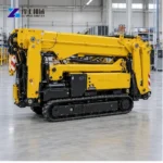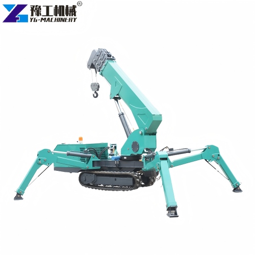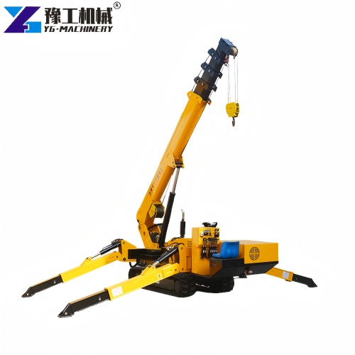
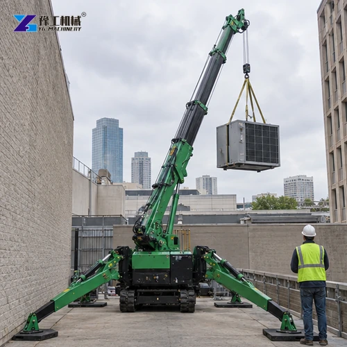

A spider crane carries a compact tracked base, deployable outriggers and a boom-and-winch system to a constrained lifting position. For rooftop HVAC work, compact access is only the first check: the setup must also cover the real load radius, rigging height, approved support surface and final placement path.
Related product information: 3 ton spider crane and 5 ton spider crane.
How Is a Spider Crane Configured for Rooftop HVAC Lifts?
A spider crane combines a compact tracked carrier with deployable outriggers and a lifting boom. The tracks help position the machine through a constrained route; the outriggers establish its support footprint; the boom, winch and approved rigging handle the load. Compact transport width alone does not establish that the crane can pass every doorway or work safely at the required radius.
For rooftop HVAC work, the crane may need to be carried to the roof by another lifting method, assembled in a restricted area and set on approved support. Confirm the delivered crane configuration, outrigger mats, hook and controls against the job plan. The building structure and access route require project approval; they are not verified by the crane’s headline capacity.
Selection follows the actual load path: move the crane to the setup point, deploy supports, lift the unit over the edge or obstacle, and land it at the prepared curb. Load weight, center of gravity, radius, hook height, rigging and wind conditions shape the usable capacity. The lift chart and competent lift plan govern the final decision.
Define the HVAC Load and Final Placement
Record the equipment model, verified lifting weight, dimensions, center of gravity and manufacturer lifting points. Add spreader requirements, shipping frame and any components that remain attached during the lift.
Mark the final curb or support, required orientation and placement tolerance. The lift is not complete when the unit reaches roof level; the crane and rigging must allow controlled landing without damaging the cabinet, curb or nearby services.
Use the HVAC unit’s verified lifting weight, dimensions and center of gravity, including any frame or accessories that stay attached. Check its lifting points and spreader requirement before selecting the spider crane configuration.
Send the HVAC unit’s verified weight, dimensions, center of gravity, planned radius and landing point; those values are needed to check the spider crane’s load chart for the actual lift.
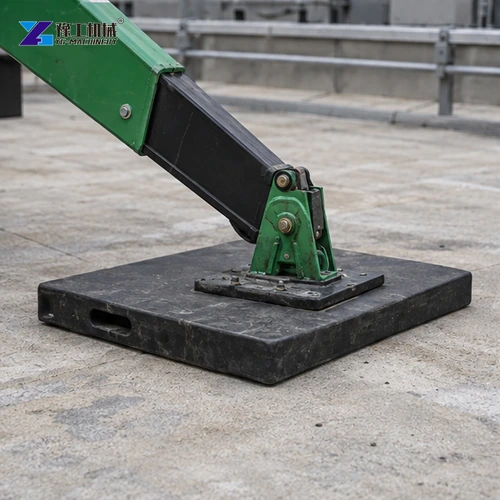

Calculate the Spider Crane Lift Radius and Height
Draw the crane position, boom path, roof edge, parapet, obstacles and final hook point. Capacity must be read at the real radius and hook height, not from the headline maximum capacity.
Include rigging height between the hook and load. Slings, spreader bars and shackles consume headroom and can increase the required boom position.
Use the crane’s load chart for the actual setup and working radius, then include hook block and rigging height in the clearance check. The rated maximum at a shorter radius does not answer whether the unit can clear the parapet and land at the planned position.


Verify Roof Access and Structural Support
Plan how the spider crane will reach the roof—by freight lift, temporary opening or a larger crane. Measure each doorway, lift car, ramp and turn, including transport weight and separately carried mats.
A qualified party must approve roof loading, travel path and outrigger reactions. Plan mats or load spreading from the actual support arrangement. Do not infer roof suitability from machine weight alone.
At the rooftop setup point, compare each outrigger position with the approved support area, roof edge, openings and obstacles. The available footprint and support condition determine whether the spider crane can be set up at the planned lift point.

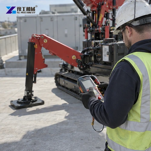
Plan Outriggers, Rigging and Work Zones
Lay out each outrigger within the available roof area and keep clear of edges, openings and weak zones. Verify level, extension, mats and exclusion areas before the load arrives.
Use an approved lift plan with rated rigging, tag lines and defined communication. Wind, visibility and rooftop access can stop the operation even when crane capacity is sufficient.
Use mat dimensions and outrigger limits for the exact crane configuration when laying out the work zone, then mark the exclusion area so workers and building occupants remain clear of the lift.
Prepare a Rooftop HVAC Crane Quotation
Send roof drawings, crane access route, unit data, lift radius, hook height, structural restrictions, rigging list, power preference and destination. Identify whether the crane must be lifted to the roof by another machine.
Request the crane model, hook block, outriggers, mats, remote control, rigging options, transport, commissioning, documents and spare parts separately. Final lift approval remains project-specific.
Separate any access crane, local rigging crew, roof protection and lift planning from the spider-crane supply unless the offer explicitly includes them; these project services can otherwise be mistaken for machine accessories.
For a rooftop HVAC lift quotation, send the unit weight and dimensions, center of gravity, lifting points, required radius and hook height, roof access route, setup footprint, structural restrictions and destination. These details let the crane configuration be checked against the actual pickup and landing positions.
Coordinate Delivery, Trial Setup and Final Handover
Coordinate the HVAC delivery truck, access crane if needed, spider-crane setup, rigging crew and mechanical contractor. A missed time window can leave the unit on the ground or the crane on the roof without the load. The lift plan should name who controls each handoff and who can stop the work.
Before the production lift, complete the approved no-load checks and, where required, a controlled trial setup. Verify controls, limit devices, hook, wire rope, outriggers, mats and communication. Recheck radius and support conditions after positioning because small changes on a constrained roof can change the load chart point.
Protect the roof membrane, parapet and installed services during travel and setup. Plan drip control, track protection and a route that avoids fragile covers or concealed openings. These measures belong in the project package even though they may be supplied locally rather than with the crane.
Handover should record crane model, configuration, actual load, radius, rigging, weather limits, setup photographs and inspection results. The equipment supplier can confirm machine scope and documentation, while the appointed lift team remains responsible for the site-specific lift and authorization.
At delivery, check the crane identity and supplied configuration against the quotation and packing list, including the hook, controls, outriggers and support mats. Record any missing or changed items before commissioning and familiarization.
Commissioning and operator familiarization should cover setup limits, load-chart use, controls, emergency functions, daily inspection and packing. Site-specific lift planning, structural approval and rigging inspection still belong to the appointed competent parties and must be complete before operation.
Spider Crane for Rooftop HVAC Lifting FAQ
No. Check the exact crane load chart at the planned radius and hook height, including rigging weight, then confirm the access and setup footprint. A qualified project reviewer must approve roof capacity and outrigger reactions.
Record the verified unit weight and center of gravity, crane position, working radius, hook height, rigging, parapet clearance, outrigger locations, support mats, exclusion zone and final landing orientation.
Measure the complete route, including doors, turns, lift cars and floor limits. If the crane itself must be lifted to the roof, identify the assisting machine and its separate lift plan before the HVAC unit delivery is scheduled.