
Spider crane price depends on the lift geometry and the supplied package, not on rated capacity alone. Quotes can differ when the required working radius, hook height, outrigger arrangement, access, power option, rigging and delivery scope differ. Start with the verified gross load and the farthest point in the planned load path, then compare the allowable chart rating at that point.
A published model maximum is not a working load chart. The model table below transcribes the capacity, radius/load datum where listed, transport envelope and machine mass shown in YG’s published spider-crane specification table. It does not establish allowable load for every boom length, slew sector or outrigger setup. The source does not state a load at the YG-8 maximum radius, so obtain the chart before treating that reach as usable capacity.
How Do Outriggers and the Load Chart Affect Spider Crane Stability?
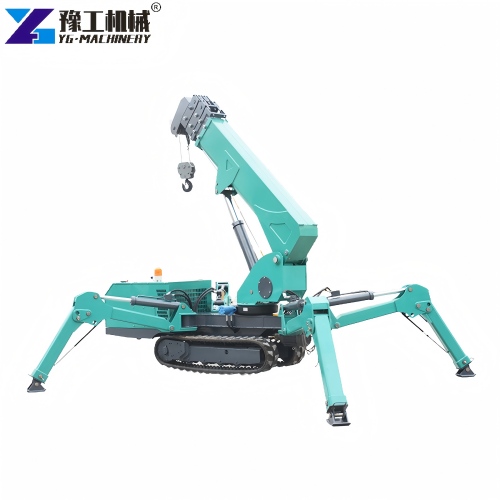
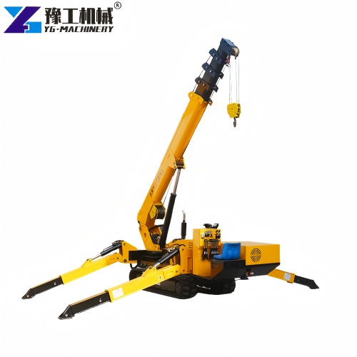
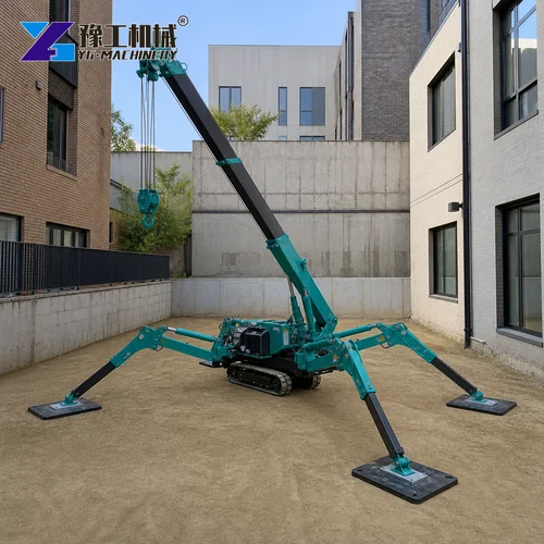
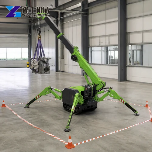
The crawler tracks move the machine into position, but the outriggers create the working support polygon for lifting. Each jack transfers a portion of the crane, attachment and lifted-load forces into the floor or ground. As the boom slews, the most heavily loaded outrigger changes. Dynamic effects from starting, stopping, wind or a swinging load add to the static reaction, so setup must follow the manufacturer’s load chart and operating manual rather than visual judgment.
A wide, symmetrical stance generally provides the largest support area. Real sites often contain walls, pits, production equipment or pedestrian routes that prevent full extension. Many modern cranes offer several approved outrigger positions; each position has a corresponding rated-capacity chart or control-system limit. If the exact configuration is not documented, treat it as unavailable. Improvised half positions can place the load outside the stable polygon before the operator recognizes the problem.
Before comparing models, ask suppliers for charts covering every permitted outrigger pattern, not only the best configuration. Confirm whether the system detects each leg position automatically, how it limits unsafe boom movements and whether the display shows the current allowable load. These controls support the operator, but they do not replace competent planning or ground assessment.
CHECK CAPACITY AT MY WORKING RADIUS
What Lift Details Should a Spider Crane Price Request Include?
Record the load weight, load dimensions, center of gravity and approved lifting points. Add the mass of the hook block, slings, shackles, spreader beam, vacuum lifter or other below-the-hook equipment. The resulting gross load is the figure to compare with the capacity chart. If the weight is estimated, use a conservative verified value; packaging labels and supplier drawings are more reliable than appearance.
Next measure the horizontal working radius from the crane’s center of rotation to the load’s center of gravity at the most demanding point of the lift. Include the pickup, travel and final placement positions. Also determine hook height, required clearance above the load, building height, boom-tip clearance and any need to reach over an obstruction. A short pickup radius does not help if final placement occurs farther away.
Draw a plan view and elevation. Mark the machine body, outriggers, load path, walls, columns, doors, overhead services and exclusion zone. This small exercise often reveals that access width or boom clearance—not nominal capacity—is the controlling constraint. For compact alternatives, compare the 3-ton spider crane specifications, 5-ton spider crane specifications and tracked mini crane transport dimensions pages against the measured geometry.
How Does Working Radius Affect a Spider Crane’s Rated Load?
| Model | Rated capacity | Published maximum radius | Transport dimensions | Total weight |
|---|---|---|---|---|
| YG-3 | 3 t | 8.83 m at 0.15 t | 2950 × 980 × 1560 mm | 2700 kg |
| YG-5 | 5 t | 14 m at 0.5 t | 5000 × 1500 × 1900 mm | 6200 kg |
| YG-8 | 8 t | 16.5 m; load at this radius not stated in the source table | 5000 × 1600 × 2180 mm | 7200 kg |
Working radius is a horizontal distance, not boom length. Increasing radius increases overturning moment even when the load weight remains unchanged. That is why rated capacity usually drops quickly as the boom lowers or telescopes. Read the row for the actual boom length and the column for the actual radius, then use the lowest applicable rating across the planned path.
Capacity charts may differ by outrigger extension, boom section, jib use and operating sector. Some ratings are limited by structural strength while others are limited by stability. Do not interpolate upward between chart values. If the measured radius lies between two entries, use the more conservative entry unless the manufacturer specifies another method. Keep a reserve for measurement uncertainty and normal operational variation.
The crane’s moment limiter or rated-capacity indicator is an essential safeguard, but the lift should already be valid on paper. Confirm that sensors, alarms and emergency stops function during pre-use checks. An alarm is a stop signal, not permission to repeatedly approach the limit.

How Do Ground and Outrigger Conditions Affect Setup?
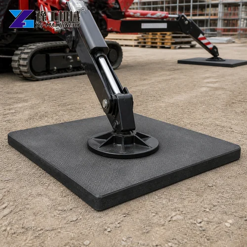
A compact crane can create high point loads at its outrigger feet. Concrete thickness, reinforcement, suspended slabs, underground services, trenches, basements, backfilled areas and floor openings all matter. Obtain allowable bearing information from the site owner or a qualified engineer when the support condition is uncertain. A visually sound slab may not be designed for concentrated crane reactions.
Outrigger mats spread reaction over a larger area. Size them from the maximum expected outrigger load and allowable ground bearing pressure, while also checking mat strength and edge distance. Place mats flat on a prepared surface, center each foot and keep the jack vertical. Timber scraps, loose blocks and stacked irregular packing can split or eject under load.
Recheck level after the crane is raised onto its outriggers. If a leg settles, the lift must stop and the support must be corrected. Never use the hydraulic jacks to compensate for ground that is continuing to move. Record the approved setup so the next shift does not unknowingly alter a critical mat or barrier.
REVIEW OUTRIGGER AND GROUND CONDITIONS
Will the Spider Crane Fit the Route and Work Area?
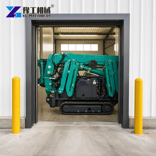
Measure door width and height, corridor turns, ramp angle, floor loading and transport weight before delivery. Retracted dimensions should include any attachment, hook or removable counterweight needed for travel. Protect finished floors where required and verify that ramps can carry the machine. A spotter should guide blind corners and keep pedestrians outside the travel path.
For indoor work, choose an electric or battery mode when available and suitable. Engine exhaust, ventilation, noise, charging, cable routing and fire precautions must be addressed in the method statement. Electric operation reduces local emissions but does not change lifting limits. The same outrigger, radius and exclusion-zone rules still apply.
Compact access is valuable only when the crane can also deploy safely at the work point. A machine that fits through a doorway may still need more floor area for its outriggers and tail swing. Verify both travel envelope and operating envelope on the site drawing.
Which Power and Control Options Belong in the Quote?
Remote control gives the operator freedom to stand where the load, landing point and signaler are visible. The operator should select a position outside pinch zones and away from the potential fall path. Test command direction at low speed before lifting, and maintain secure possession of the transmitter so no unauthorized person can activate the crane.
Battery-electric and mains-electric options suit sensitive indoor projects, while diesel power supports remote outdoor work. Compare duty cycle, charging time, cable requirements, ambient temperature and expected daily lifts. Ask whether simultaneous charging and operation is permitted and how emergency recovery works after a power loss.
Smooth proportional controls are especially useful for glazing, machinery installation and façade work. However, precision also depends on appropriate rigging, clear communication and a stable load. Speed settings should match the task, with slow modes used near final placement.
CHECK SITE ACCESS AND POWER OPTIONS
How Do Rigging and Attachments Change the Lift Package?
Use certified rigging with adequate working load limit and a configuration suitable for the load’s center of gravity. Sling angles can multiply leg tension; account for that effect rather than dividing weight equally. Protect slings from sharp edges and confirm that shackles, hooks and attachment points are compatible. Include every accessory in gross suspended weight.
If the lift needs a vacuum lifter, spreader beam, special hook or other attachment, list its model, weight, capacity and compatibility in the quote request. The attachment and rigging weight count toward the gross suspended load; ask for them as separate line items so competing offers cover the same package.
Side pulling is prohibited because crane charts assume a freely suspended vertical load. Align the hook over the load before tensioning. If the load snags or cannot be lifted cleanly, lower it and correct the obstruction instead of increasing force.


What Lift-Planning Details Should Buyers Confirm?
For a comparable quote, provide a plan showing pickup and placement points, the maximum radius along the load path, hook height, access route, approved outrigger arrangement, support surface and required accessories. Ask the supplier to identify the load-chart page and configuration used for the recommendation.
The site lift plan should define checks, stop-work conditions, operator and signaler roles, exclusion zones and the approved setup procedure. A quote or model recommendation does not replace the project’s competent lift planning or local requirements.
State the site’s wind, visibility and weather limits in the project brief. Confirm the applicable equipment and attachment instructions; compact size does not by itself establish suitability for every outdoor condition.
COMPARE MY LOAD-CHART REQUIREMENTS
Which Inspection and Service Costs Should Buyers Compare?
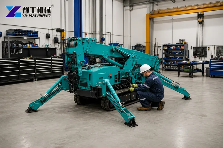
A pre-use inspection should cover outriggers, pins, pads, cylinders, hoses, crawler tracks, wire rope, hook safety latch, boom sections, limit switches, controls, alarms and fluid leaks. Verify inspection status and review the operator manual. Defects affecting structural, hydraulic or safety systems require removal from service until assessed by a competent person.
Planned maintenance should follow operating hours and calendar intervals. Lubricate specified points, maintain batteries, inspect rope reeving, check fastener torque where required and keep sensors clean. Record faults and repairs so recurring problems become visible. A compact machine often works in dusty or restricted areas, making daily cleaning important for reliable cooling and inspection.
Transport locks, outrigger pins and removable components deserve special attention after relocation. Complete a new setup check whenever the crane moves, even within the same building.
What Should a Spider Crane Price Comparison Include?
Compare each candidate at the actual working radius, hook height and approved outrigger configuration. Then compare transport envelope and working footprint. Ask each seller to identify the relevant load-chart data and to list rigging, mats, controls, power equipment, delivery, commissioning, training and warranty separately so the quoted scope is comparable.
Purchase price is only one component of cost. Include delivery, lifting accessories, mats, inspections, operator training, batteries, charging equipment, maintenance, wire-rope replacement and expected downtime. Service access and parts availability can be more valuable than a small difference in initial price, especially when the crane supports time-critical installations.
For a project-specific comparison, send the verified gross load, pickup and placement radii, required hook height, access dimensions, support-surface information, available outrigger positions, power preference and destination. This gives the team a defined basis for checking the model and preparing a quotation.
REQUEST A CONFIGURED SPIDER CRANE QUOTE
Spider Crane FAQ
No. Maximum capacity normally applies only to a limited short-radius configuration. Capacity falls as radius and boom length increase. Always use the chart for the actual boom and outrigger setup.
They may be required because an outrigger creates concentrated load. The slab and supporting structure must be verified, and mats should be sized from reaction and allowable bearing pressure rather than chosen by appearance.
Only if the manufacturer explicitly provides a pick-and-carry procedure and rating for that model and configuration. Standard stationary lifting charts do not authorize travel with a load.
Provide load weight and dimensions, rigging weight, pickup and placement radii, required hook height, access width and height, ground or floor details, power preference and site location.
Request a Spider Crane Quote for the Planned Radius
A reliable selection starts with the lift geometry and support conditions. Share your project details with YG Machinery for a model comparison, configuration proposal and commercial quotation.