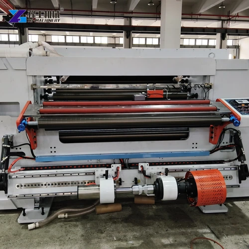
Complete setup starts with a clean stopped machine and an empty web path.
Check the unwind stand, guide rollers and material direction before loading.
Slitting machine setup converts an approved roll specification into a safe, repeatable path through unwinding, guiding, cutting and rewinding. The operator is not simply entering a width and speed. Parent-roll condition, core grip, web direction, knife position, trim, tension zones and finished-roll removal must all agree before production begins.
Prepare a written job sheet for the exact material and order. It should state parent-roll width and diameter, core, winding direction, lane widths, trim, finished diameter, quantity, labels and acceptance limits. Use the installed machine manual and site safety procedure for loading, threading, guarded checks and stored-energy control.
This setup guide supports the YG paper slitting machine range and focuses on decisions that should be verified during a trial cut.
Confirm the Roll Specification Before Slitting Machine Setup
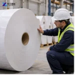
Identify the web material, thickness or basis weight, coating, splice locations, defects and storage condition. Measure the parent roll and confirm the core instead of relying only on a supplier label. A damaged core, uneven hardness or telescoped parent roll can create tracking and tension problems before the knife station.
Calculate the lane pattern and total trim. Add every finished width, internal trim if required and both edge trims; the result must fit the usable parent web. Record tolerances and the inspection tool. If the order requires several patterns, issue a separate setup sheet for each rather than writing changes by hand during production.
Define how finished rolls will be handled and labelled. Core length, maximum diameter, roll mass and unloading space influence shaft selection and rewind planning. The job cannot be approved if the rolls can be produced but not removed or traced safely.
Send the parent-roll and finished-roll specification so YG can check whether the planned job fits the machine range.
Inspect the unwind shaft or chucks, lifting device, locking components and roll orientation before movement. Use rated handling equipment and keep personnel outside the suspended-load and pinch-point zones. Confirm that the roll will unwind in the required direction and that the web surface that must remain protected will not contact a contaminated roller.
Center the roll against the machine reference and secure the core. Check lateral position, core grip and obvious runout before applying production tension. A roll that shifts on the shaft can defeat web guiding and move the entire slit pattern even when the knives remain fixed.
Set the initial unwind brake or drive using the material recipe and roll condition. High resistance can stretch or curl the web; low resistance can create slack and wrinkles. The value must be reviewed again as diameter falls during the trial.
Confirm the control side, emergency stop and roller access before threading.
Thread the web through the specified rollers without twists or loose spans.
Thread the Web Through the Slitting Machine Roller Path
Follow the specified threading diagram through guide rollers, sensors, tension devices, traction rollers and the knife station. Do not improvise a shorter path to save time. A missed roller changes wrap angle, traction and tension response and may place the web outside a guard or sensor range.
Keep the web flat and centred while threading. Remove folds at the source rather than pulling one edge harder. Check that edge or line sensors see the intended target and that the guide correction direction is correct before the web reaches operating speed.
Inspect every roller surface for adhesive, dust, damage and foreign material. A small deposit can mark a sensitive web or create a repeating tracking error. Clean only with the approved method and keep hands clear of nip points whenever power is available.
Provide the web direction, core and threading constraints to review the unwind and guide arrangement.
Clean the knife shafts, spacers and holders, then build the slit pattern from the machine reference. Verify each lane width and the cumulative total. Include trim handling in the setup: unsupported trim can wrap around a shaft or pull the outer lane away from its intended path.
Set knife clearance and overlap for the approved blade system and material. Rotate through the permitted manual check, confirm there is no contact outside the cutting edges and restore every guard. The paper slitter edge-quality guide helps connect knife changes with the finished-roll inspection record.
Mark the lane order and destination rewind position. A correct knife pattern can still produce mixed rolls if cores, labels and lanes are not mapped before startup. Use a second-person check for critical width orders.
Rewind cores and lanes must align with the selected slit widths.
Secure the rewind shaft and verify core grip before the trial run.
Use YG Model Limits During Slitting Machine Setup
YG-1300, YG-1600 and YG-1800 provide three maximum web-width ranges with matching power, weight and machine dimensions. All three list a 1400 mm maximum unwind diameter, 1000 mm maximum rewind diameter, 30 mm minimum slit-width reference and up-to-350 m/min slitting speed.
Treat these as model boundaries, not universal production settings. The selected material, lane count, knife method, roll hardness and quality target determine the usable recipe. Check plant voltage, floor space, loading aisle and finished-roll handling against the exact model before installation and again before a new job family is introduced.
Parameter
YG-1300
YG-1600
YG-1800
Maximum web width
1300 mm
1600 mm
1800 mm
Maximum unwind diameter
1400 mm
1400 mm
1400 mm
Minimum slit width
30 mm
30 mm
30 mm
Maximum rewind diameter
1000 mm
1000 mm
1000 mm
Slitting speed
Up to 350 m/min
Up to 350 m/min
Up to 350 m/min
Total power
24 kW
26 kW
30 kW
Power supply
380 V / 50 Hz
380 V / 50 Hz
380 V / 50 Hz
Machine weight
4000 kg
4500 kg
5500 kg
Overall size (L×W×H)
3300×3150×1930 mm
3300×3450×1930 mm
3300×3650×1930 mm
Use the complete model row when comparing capacity, power, weight and installation space. Do not combine the largest value from one model with the dimensions or power of another.
Share the required width, diameter and utilities to match the correct YG model and installation envelope.
Start with the approved material recipe at low speed. The unwind must release the roll without slack, while traction and intermediate zones hold a stable web through the knife station. The rewind system then changes torque as roll diameter grows. One displayed number cannot describe all three functions.
Watch edge position, wrinkles, lane separation, roll hardness and end-face alignment during acceleration and deceleration. Excess tension can stretch the web, lift coatings or crush cores; insufficient tension can create loose rolls and telescoping. Change one zone at a time and record the effect on all lanes.
Confirm shaft inflation or chuck grip and align every core with its lane. If one roll winds differently, inspect core condition, lane thickness, shaft or differential element and local web path before raising overall tension. The slitting machine maintenance record helps separate setup from component wear.
Set low initial tension and increase only after the web tracks steadily.
Use a short trial cut to confirm width, edge quality and rewind alignment.
Run a Low-Speed Trial Cut and Approve the Setup
Run enough material to form stable lanes and representative rewind rolls. Measure every width, not only the centre lane. Inspect both cut edges, trim removal, web tracking, core alignment, end faces, roll hardness and the behaviour during start, stop and speed change.
If a result fails, identify the defect, lane and operating condition before changing the machine. Width errors may come from spacing, web movement or measurement; rough edges may come from knife setup or material; telescoping may come from alignment, torque or core grip. Multiple simultaneous changes make the real cause impossible to confirm.
After acceptance, save the material lot, parent-roll data, lane pattern, knife arrangement, tension values, speed range, trim path and inspection results. A controlled record makes repeat production faster and gives maintenance a baseline when quality changes later.
Send the approved slit pattern and quality limits for a complete machine and commissioning quotation.
Prepare Slitting Machine Setup Data for a New Order
Send YG the material, parent-roll dimensions, core sizes, finished widths, trim, finished diameter, roll mass, target speed, edge standard and plant utilities. Add handling limits, dust or static requirements and photographs of the available production space.
Ask the quotation and technical file to identify the model, unwind arrangement, guiding, knife method, rewind shafts, unloading, trim collection, controls, guards, accessories and test scope. Keep optional upgrades separate so the order can be checked line by line.
Use the final approved drawing and manual at commissioning. A complete setup record should follow the machine from trial to production, rather than being reconstructed after a quality complaint.
Slitting Machine Setup for Stable Paper Roll Production FAQ
What should be checked first during slitting machine setup?
Confirm the material, parent roll, core, winding direction, slit pattern, trim, finished roll and acceptance limits before loading.
Why should the web follow the specified threading path?
Roller wrap, guiding and tension response depend on that path; skipping a roller can destabilize tracking and rewinding.
Should production start at the maximum listed speed?
No. Begin with a controlled low-speed trial and raise speed only after cutting, tracking and rewinding remain acceptable.
What setup data should be saved for repeat orders?
Save material lot, roll data, slit pattern, knives, tension zones, speed range, trim path, core and inspection results.
Prepare the Final Slitting Review
A stable slitting machine setup is a verified chain from roll identification to finished-roll acceptance. Keep the approved job sheet with the machine record and send the same inputs when YG reviews a new material or production requirement.