
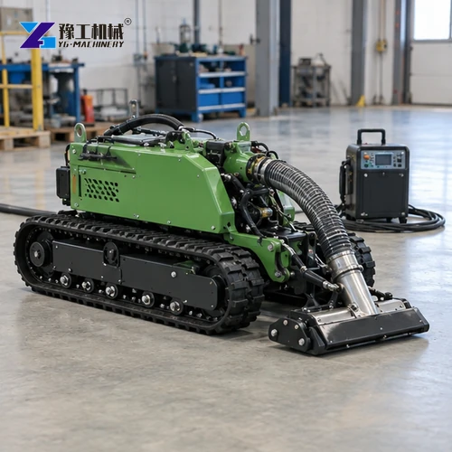
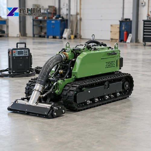
A wastewater treatment dredging robot is the pickup and conveyance stage of a sludge-removal package. Basin geometry, sediment, access, hose routing and the receiving system must be reviewed together before a buyer compares robot configurations.
Related product information: underwater dredging robot and hydraulic dredge pump.
Where Does a Dredging Robot Fit in Wastewater Treatment?
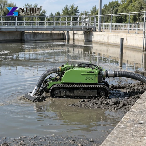
A tracked dredging robot is intended to work over sediment in a basin or channel where ordinary access may be difficult. The machine can support sludge removal, but a workable wastewater project also needs an approved deployment route, an operating plan and a receiving process that can accept the material collected.
Selection therefore begins with the plant’s layout and process boundaries, not a generic claim about basin size. Map the obstacles, sludge zones, access and retrieval points, then confirm utilities and downstream handling with the facility team before specifying the complete equipment package.
Dredging Robot Models for Wastewater Treatment
| Model | Working Width (mm) | Dimensions (mm) | Weight (kg) | Pump Outlet (in) | Motor Power (kW) | Max Particle (mm) |
|---|---|---|---|---|---|---|
| YG-500 | 500 | 1500 × 500 × 650 | 320 | 3 | 22 | 15 |
| YG-600 | 600 | 1500 × 600 × 650 | 350 | 3 | 22 | 15 |
| YG-700 | 700 | 1600 × 700 × 650 | 380 | 4 | 30 | 38 |
| YG-800 | 800 | 1600 × 850 × 700 | 400 | 4 | 30 | 38 |
| YG-900 | 900 | 1650 × 960 × 750 | 420 | 4 | 30 | 38 |
| YG-1200 | 1200 | 1900 × 1200 × 750 | 500 | 4 | 45 | 60 |
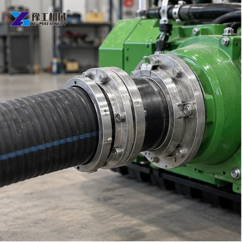
Choose working width to suit basin passages and sediment areas, then check machine dimensions and weight against access, retrieval and transport limits. Match the pump outlet, motor power and passable particle size to the slurry and downstream handling route. These machine specifications do not predict daily output: solids concentration, hose length, elevation, bends and receiving equipment all affect actual throughput. Compare the underwater dredging robot with the basin and dewatering requirements.
Map the Treatment Basin and Sediment Zones
Provide basin drawings, operating water level, floor profile, baffles, columns, inlets, outlets, walkways and any areas that cannot be disturbed. Mark sediment depth and zones that need cleaning. A basin name alone does not show whether the crawler can reach the material or turn around it.
Clarify whether treatment continues during the work, which process units remain online and when the basin can be isolated or partially drained. Operations staff should identify permitted work windows, flow changes, alarms and stop conditions before equipment is mobilized.
Use a marked basin plan to distinguish accessible floor from baffle shadows, corners and areas around columns. Note where sludge depth is estimated and where it has been measured so the supplier understands the confidence of the site information.
Share a marked basin plan, sediment map, access opening, deployment and recovery points, hose route and receiving-system limits; these show whether the robot can reach the sludge and discharge it to an available treatment stage.

Describe Wastewater Sludge and Debris
Record sludge depth, consistency, settled solids, fibres, rags, grit and any unusual debris based on the facility’s own sampling or operating information. Conditions may vary between the inlet zone, corners and baffle areas, so describe representative locations instead of one assumed material.
State any known chemical, biological or environmental controls through the site’s approved process. The dredging robot is a material-handling machine; it does not classify waste, neutralize contaminants or replace the facility’s confined-space and wastewater procedures.
Take representative sludge samples only under the facility’s approved safety and sampling procedure. Photos and process notes can help describe fibres or settled material but do not substitute for required laboratory or waste characterization.

Plan Access, Deployment and Retrieval
Measure gates, stairways, hatches, walkways, lifting points, ramp angles and the route from unloading to the basin. Confirm the available headroom, surface condition and clearance around handrails or pipework. The full handling path matters because the unit must be delivered, deployed and retrieved, not only fit through one opening.
Identify lifting equipment, rigging points, operator positions, cable or hose routing and a recovery plan if the machine stops in a difficult area. Keep personnel out of unprotected water or sludge zones and follow the facility’s isolation, electrical and access controls.
The deployment drawing should show every doorway, hatch, turn, lifting point and route to the water. Include the retrieval method before the machine enters the basin.
Before selecting a wastewater dredging robot, measure the basin passage and access opening, map sediment depth and type, and mark deployment and recovery points. Add the hose route and receiving-system limits; together these show whether the machine can reach the sludge and move it to an available treatment stage.
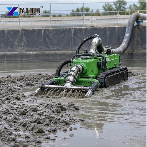

Connect Sludge Removal to the Treatment Process
Define where collected material goes next: a receiving tank, screening stage, dewatering unit, tanker or another approved interface. The facility must confirm allowable feed condition, available footprint, utility connections, return-water route and who manages the solids after collection.
Coordinate equipment operation with process staff so a change in basin flow or receiving capacity does not leave material without an accepted destination. State the communications method, monitoring responsibility and response when the downstream stage pauses or the sludge changes.
The receiving system must be reviewed by the treatment operator. A machine may move sediment, but the plant still determines whether the feed can enter its process and how solids are contained or removed.
Prepare a Wastewater Dredging Robot Enquiry
Send the basin plan, water levels, sediment map, sludge description, obstacles, access measurements, deployment method, utilities, operating window and discharge destination. Include photos of the hatch, walkway and working zone, and identify any process restrictions imposed by the facility.
Ask the offer to itemize the tracked dredging unit, working head, controls, hoses or cables, deployment and retrieval accessories, wear parts, documents, packing and commissioning scope. Keep facility shutdowns, waste classification, dewatering approval and site lifting separate unless the contract states otherwise.
A complete request lists the equipment boundary and site interfaces separately. Ask who supplies power, lifting gear, hoses, operators, dewatering, disposal and process monitoring.
Share a basin drawing, water depth, sludge type, access and recovery route, hose distance, and the receiving or dewatering setup. These details help match the robot and pump arrangement to your treatment process.
Set Operating, Recovery and Acceptance Checks
Agree a pre-start checklist with facility operations covering basin status, water level, communications, exclusion areas, utilities, machine function, hose or cable condition and receiving-system availability. Do not begin if an isolation or process prerequisite is missing.
Define how the crew will detect a blockage, loss of control, unexpected material or downstream interruption. Stop, isolate and recover the unit by the approved method; do not send personnel into a hazardous basin to retrieve equipment without facility authorization.
Acceptance should record the agreed basin zones addressed, equipment configuration, interruptions, recovered material route and outstanding sediment areas. A site-specific record helps the plant decide whether the next pass or a different method is required.
For a treatment plant with several cells, rank basins by sediment condition, isolation opportunity and receiving-system availability. A smaller accessible cell may be a better first trial than the largest basin if it lets the operations team verify hose routing, controls and solids handling without disrupting the entire process.
Record the sludge destination and the boundary between dredging and dewatering. The pump outlet size and model data identify machine interfaces, but they do not establish a guaranteed solids rate; concentration, debris, elevation, hose bends and downstream equipment all affect the actual process.
Wastewater Treatment Dredging Robot: Basin Selection FAQ
Provide a basin drawing, water levels, sediment zones, obstacles, access and retrieval route, sludge description, operating restrictions, available utilities and the receiving process.
No. Floor profile, baffles, sludge, deployment and recovery access, utilities and downstream acceptance all affect whether the equipment fits the treatment operation.
Not by default. Confirm the written supply boundary for receiving, screening, dewatering, containment, transport and disposal; these may be separate plant or contractor responsibilities.


