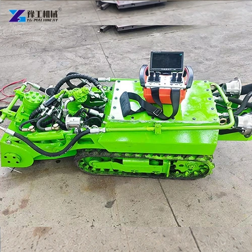
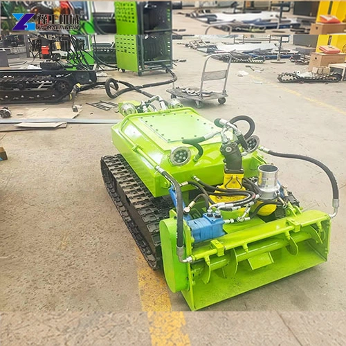
A robotic dredge needs a work plan that connects the area being cleaned with the movement of the crawler, its hoses and the receiving process. Cleaning an accessible strip is different from completing an entire basin. A practical plan makes progress visible and prevents unfinished corners, poorly managed material or an unavailable receiving area from controlling the job.
With a tracked YG system, the floor, material and receiving process determine the working sequence. Define the areas to be cleaned and their acceptance requirement before using a nominal machine rating to plan the job. A realistic schedule follows the site’s conditions and the work needed to reach the required bottom condition.
Define the Sediment-Removal Task Before Organizing Passes
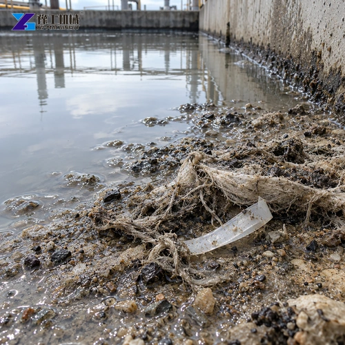
Start with the material and the area that needs to be cleaned. A uniformly settled layer can be approached differently from localized deposits near an inlet, debris around structures or changing sediment thickness. Record those differences before dividing the floor into working areas. Otherwise, a plan based only on surface area can underestimate the zones that need a different approach.
Identify material that changes the handling task. Stones, plastic, fibres and timber can behave differently from fine sediment, even when some pieces appear small. Decide how unsuitable objects will be managed rather than assume the robot will pump everything away. The particle specification is one selection input; the shape and nature of debris also matter.
The tracked underwater dredging system provides the equipment starting point. The job plan must add the site’s floor conditions, obstacles and material destination. Keep the operating environment within the selected system’s suitability, especially where the basin contains materials requiring a specific handling process.
Divide the Floor Into Zones the Operator Can Track
Working zones give the operator and supervisor a shared way to describe progress. Use actual boundaries such as a basin wall, inlet area, structural feature or accessible strip. The zones should help the team reach every planned area without repeatedly moving the crawler across a completed section. An arbitrary grid is less useful when access or obstacles determine the route.
Organize the sequence around entry and recovery. The first zone should allow the system to establish a workable route, while the last should leave a practical way to recover the robot and manage its connections. Keep track of incomplete areas as the work advances. This is especially important around corners or structures that a straight pass may not cover fully.
A zone record can contain:
- Its position and the material or obstacles expected there.
- The planned entry, working direction and accessible recovery route.
- The inspection method used to establish its starting and remaining sediment condition.
- Any unfinished strip or obstruction requiring separate attention.
This gives a robotic dredge a measurable work sequence without promising that every zone needs the same time or number of passes. It also lets the team distinguish a difficult deposit from a machine or receiving-system interruption.
Share the basin shape and difficult areas to discuss how the selected system fits the work sequence.
Move the Crawler Without Letting Hoses Control the Route
The crawler, hydraulic connections and discharge arrangement need a coordinated path. A hose pulled across an obstacle or trapped behind a structure can restrict movement even when the machine itself has adequate access. Lay out the supporting equipment and connection routes so they can be managed as the robot enters the next working area.
Allow for changes in route as zones are completed. A hose position suitable for the first strip may become awkward on the far side of the basin. Plan where connections can be managed from the bank and how the machine will return. Avoid making recovery an afterthought once the crawler has reached its most distant working point.
The standard hydraulic hose entry in the model table describes the supporting hydraulic connection. It is not a statement that every discharge route has the same allowable length. The hose and receiving-system discussion helps separate those parts of the job: hydraulic support, material transfer and downstream handling must be considered together but should not be confused.
YG Robotic Dredge Model Specifications
| Specifications | YG-500 | YG-600 | YG-700 | YG-800 | YG-900 | YG-1200 |
| Model | YG-500 | YG-600 | YG-700 | YG-800 | YG-900 | YG-1200 |
| Robot dimensions, mm | 1500×500×650 | 1500×600×650 | 1600×700×650 | 1600×850×700 | 1650×960×750 | 1900×1200×750 |
| Dredging width, mm | 500 | 600 | 700 | 800 | 900 | 1200 |
| Track travel speed, m/s | 3–15 | 3–15 | 3–15 | 3–15 | 3–15 | 3–15 |
| Robot weight, kg | 320 | 350 | 380 | 400 | 420 | 500 |
| Pump outlet diameter, inch | 3 | 3 | 4 | 4 | 4 | 4 |
| Pump flow rate, m³/h | 100 | 100 | 200 | 200 | 200 | 200 |
| Hydraulic station dimensions, mm | 2200×1200×1700 | 2200×1200×1700 | 2200×1200×1700 | 2200×1200×1700 | 2200×1200×1700 | 2120×1240×1200 |
| Main motor power, kW | 22 | 22 | 30 | 30 | 30 | 45 |
| Hydraulic system pressure, MPa | 0–16 | 0–16 | 0–16 | 0–16 | 0–16 | 0–16 |
| Particle size, mm | 15 | 15 | 38 | 38 | 38 | 60 |
| Reeling speed, r/min | 0–10 | 0–10 | 0–10 | 0–10 | 0–10 | 0–10 |
| Standard hydraulic hose length, m | 50 | 50 | 50 | 50 | 50 | 50 |
| Control system | Wireless remote | Wireless remote | Wireless remote | Wireless remote | Wireless remote | Wireless remote |
| Underwater LED lights | 2 | 2 | 2 | 2 | 2 | 2 |
Use the robot envelope for access and recovery planning, working width for organizing strips, and the pumping specification for the transfer-system discussion. None of these figures establishes a finished zone’s cleaning time. The travel-speed specification is also separate from the rate at which sediment is collected and removed.
YG can compare the crawler envelope and supporting equipment with the access and recovery arrangement.
Prepare the Receiving Area Before Starting the Robotic Dredge
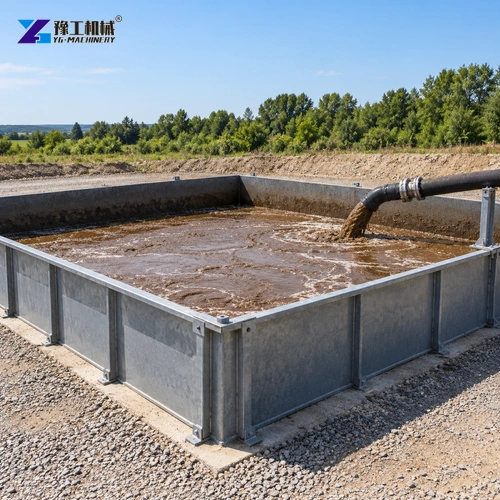
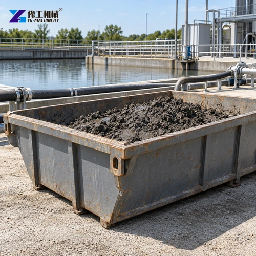
The receiving arrangement controls what happens to the material once it leaves the hose. It may involve settling, dewatering or another process appropriate to the site’s material. It needs capacity and access for the expected flow of water and sediment, plus a practical way to handle accumulated material. A full receiving area can interrupt the work even while the robot and pump remain available.
Coordinate removal from that area with the cleaning sequence. If damp solids are transferred onward, space and handling access must remain available. If water is separated, its management belongs in the site plan as well. Do not let an improvised discharge point replace the required material-handling arrangement.
For a contained basin, the wastewater-basin selection guide provides a related equipment discussion. The operational point remains simple: plan the receiving process at the same time as the robotic dredge, not after the first working area has already produced material.
Check the Remaining Sediment, Not Just the Water Appearance
Completion should be judged against the required condition of the bottom. Clearer water, a visible hose flow or a completed travel path does not prove that the planned sediment has been removed. Use an inspection or measurement method appropriate to the basin and apply it consistently to the areas being compared.
Record the result by zone. Identify residual strips, difficult corners and obstructions rather than reporting only that the machine has visited the whole basin. Where an area needs another pass or a separate method, make that decision visible. This helps keep the acceptance discussion connected to the floor condition, not simply to operating hours.
A robotic dredge work record is most useful when it connects starting conditions, the work performed and the remaining condition. It can support planning for later maintenance without inventing an efficiency percentage or assuming every future deposit will behave like the current one.
A proposal should connect the cleaning task, receiving process and the condition you need to achieve.
Robotic Dredge FAQs
Use boundaries that help organize access, material differences and progress, such as walls, inlet areas or structural features. The zones should support a practical working and recovery sequence.
No. Inspect or measure the remaining sediment using an appropriate consistent method. Water appearance and machine travel alone do not establish the condition of the bottom.
Material thickness, debris and geometry can differ between zones. Adapt the work within the equipment’s operating instructions rather than assuming equal area means equal cleaning effort.
No. Hydraulic support and material discharge serve different functions. Evaluate the discharge route, lift and receiving arrangement separately as part of the complete system.
Record the starting conditions, working zones, interruptions, remaining sediment condition and outstanding areas. This relates the equipment’s work to the actual acceptance task.
Make Each Working Area Part of a Verifiable Result
A robotic dredge contributes to a complete job when zones, connections, material handling and final checks stay coordinated. Organize the work so the operator can reach and recover the machine, the receiving process can continue, and each area has a meaningful completion check. This is more useful than estimating the whole project from one nominal equipment figure.
Include the basin layout, sediment conditions, access, receiving process and completion requirement in your inquiry.