Helical Pile Installation Equipment should be planned from the foundation design backward. Start with soil data, pile geometry, design loads and the engineer’s installation criteria. Then select the torque capacity, drive adaptor, carrier access and quality records needed to deliver that foundation. This order prevents a project from buying a machine first and discovering later that the pile connection, site route or required torque was not included.
A compact YG-32S system provides 3500 N.m rotary torque, a 20 MPa hydraulic system and crawler travel in a 1.2-ton package. Those figures define an operating envelope, not an automatic approval for every screw foundation. Screw Pile Equipment must be matched to the planned piles and ground. A Helical Pile Machine also needs a clear production method so survey, handling, installation and inspection work as one controlled process.
Helical Pile Installation Equipment Starts With Site Data
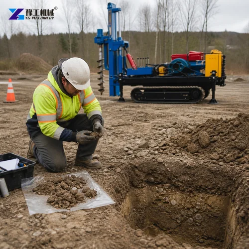
Collect the geotechnical report, structural reactions, pile schedule, finished connection level and tolerances before selecting equipment. Identify loose fill, dense layers, groundwater, cobbles, buried structures and changes across the site. The report should be interpreted by the responsible design team, because a general soil description does not establish the final pile length or installation torque.
Map access separately from foundation design. Record gate width, turning room, overhead clearance, cross slope, soft edges and the bearing condition of each work row. The YG-32S is 2300 mm long, 1300 mm wide and 2200 mm high. The route needs more than those transport dimensions because the crew must handle piles, deploy stabilizers and keep people outside the operating zone.
Define utilities and permit constraints before ground penetration. Survey marks should remain visible after the crawler enters the area. Plan where piles, adaptors and spare parts will be stored. Helical Pile Installation Equipment produces the best flow when delivery, layout and installation move in the same direction without repeatedly crossing completed work.

Complete Helical Pile Machine Specification
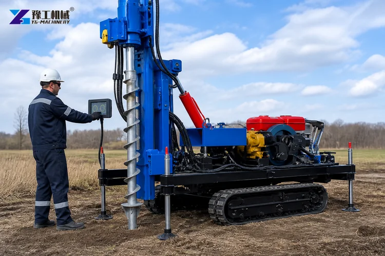
Use the complete machine specification to test the project plan. Weight and dimensions affect transport and ground support. Torque and pressure affect the selected foundation system. Carriage travel, piling height and diameter range affect tooling and pile handling. Travel speed and climbing ability help route planning but do not replace a site-specific movement assessment.
| Parameter | YG-32S Specification |
| Model | YG-32S |
| Rig Weight | 1.2 T |
| Dimensions (L x W x H) | 2300 x 1300 x 2200 mm |
| Engine Power | 32 HP |
| Rotary Head Torque | 3500 N.m |
| Hydraulic Oil Pump | Single Pump |
| Hydraulic Loading System | Cylinder Chain Pressure |
| Hydraulic Working Pressure | 20 MPa |
| Travel System | Crawler Gearbox |
| Travel Speed | 7-15 km/h |
| Cooling System | Hydraulic Cooler |
| Carriage Travel | 2.8 m |
| Piling Height | 1-3 m |
| Borehole Diameter | 50-300 mm |
| Borehole Depth | 1-30 m |
| Air Consumption | 6 m3/min |
| Suitable Rock Range | Medium Hard Rock, F=8-12 |
| Hydraulic Stabilizer Legs | 4 |
| Climbing Ability | 35 Degrees |
Record any difference between the planned pile and the standard YG-32S connection. The quotation should close those gaps with the correct adaptor, extension, guide or handling device. If the project needs more torque, another carrier or a different pile length, make that decision before production and shipping rather than relying on an improvised site modification.
How To Match Screw Pile Equipment To Torque Demand?
The engineer should provide an installation torque framework for each pile type and soil zone. It may include a minimum criterion, a maximum limit and an action for early refusal or unexpectedly low resistance. The machine operator needs a readable measurement method and a record that connects torque to the pile identification. Pressure alone should not be treated as a universal torque value without an approved correlation.
Pile diameter and helix geometry affect the resistance seen by the drive head. Larger components do not always suit a compact machine merely because they fit the adaptor. Review shaft strength, connection capacity and expected ground response. Screw Pile Equipment should be selected with reserve for normal variation while remaining inside the pile manufacturer’s limits.
Use a pilot installation to verify the assumed range before full production. Monitor alignment, depth, torque trend, penetration rate and machine support. The purpose is to validate the complete method, not to chase a single maximum number. A Helical Pile Machine that works smoothly in one zone may need another plan where the soil profile changes.
Helical Pile Machine Layout And Access Planning
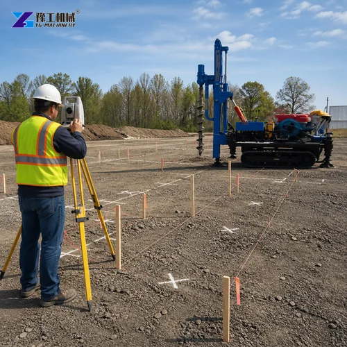
Divide the site into installation rows and select a travel direction that avoids reversing around completed pile heads. Keep survey control points outside the crawler path. Pile storage should follow the sequence without blocking emergency access or delivery routes. Mark exclusion zones wide enough for the pile length and the movement of the mast and adaptor.
Stabilizers require prepared bearing surfaces. Check whether mats are needed near trenches, recent fill or wet areas. The published 35-degree climbing ability should be considered only with the manufacturer’s travel instructions and a suitable surface. A lower practical limit may be necessary where cross slope, edge distance or stopping room creates risk.
Coordinate the equipment route with other trades. Greenhouse frames, solar racks, drainage, temporary power and excavation can compete for the same corridor. Helical Pile Installation Equipment should enter before access narrows, but only after the survey and utility controls are ready. A short logistics drawing can prevent hours of relocation during production.
Pilot Installation For Helical Pile Installation Equipment
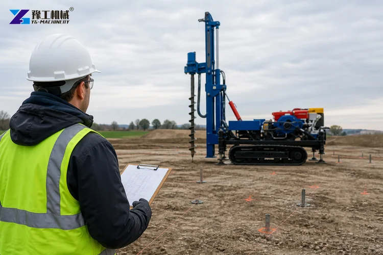
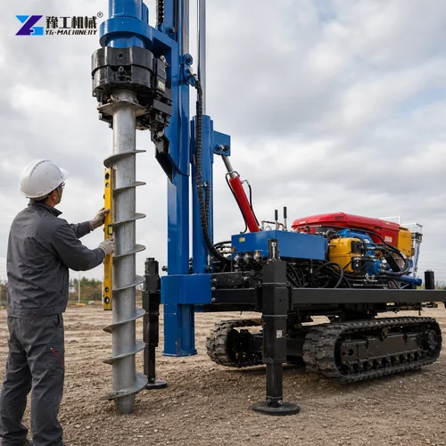
Select pilot locations that represent the expected soil zones rather than the easiest area near the gate. Inspect each pile, confirm the drive connection and establish the survey mark. Position the rig, deploy the stabilizers, set alignment and begin at a controlled speed. Record the torque trend from initial penetration to the approved final criterion.
Stop and review if the pile leans, the adaptor moves, the support settles or torque changes abruptly. The response may require repositioning, another pile detail or engineering review. Do not solve refusal by applying uncontrolled force. The pilot should also confirm the crew’s signals, pile handling method, record form and time required for safe relocation.
Inspect the finished position, level and connection. Where the project method requires load testing or another verification, coordinate it before releasing full production. A successful pilot creates a practical reference for operators and inspectors. It also gives the buyer a realistic production estimate based on accepted piles rather than travel speed alone.
Quality Records For Screw Foundations
Assign a unique pile identifier and record the design position, pile type, installation date, operator, measured depth, final level, torque trend, final criterion and any deviation. Add photographs where useful. The record should use the units defined by the engineer and remain legible after export or printing. A consistent form makes hundreds of installations easier to review.
Separate machine data from foundation acceptance. Engine power, pressure and rotary capacity describe the equipment. Depth, alignment and torque records describe the installation. The responsible professional decides whether the finished pile meets the project requirements. This distinction keeps technical communication clear when a remote YG specialist helps with equipment operation.
Review records daily for patterns. Repeated low torque, increasing refusal, alignment drift or longer installation time can identify a soil or setup change. Early review protects the schedule and gives the design team enough information to respond. A Helical Pile Machine is more valuable when its production is supported by traceable quality data.
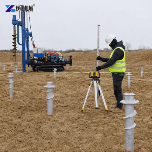

Crew Roles Around Helical Pile Installation Equipment
Define an operator, spotter, pile handler, survey contact and installation recorder. One person may cover more than one role on a small project, but the responsibilities should remain clear. Only the designated operator controls the machine. The spotter confirms the exclusion zone and communicates using agreed signals that remain visible in dust, glare or noisy conditions.
Prepare piles and adaptors outside the operating zone. Inspect threads, pins and drive faces before lifting. Never guide a rotating pile by hand or stand under a suspended component. Stop, isolate and support the system before changing tooling. Crew efficiency comes from staging and repetition, not from entering the machine envelope while it is moving.
The daily brief should cover soil zone, pile type, layout direction, weather, access changes and the response to refusal. New workers need machine-specific guidance before joining the sequence. Screw Pile Equipment can support fast work, but the pace must remain compatible with survey accuracy, handling control and complete records.
Screw Pile Equipment Cost And Schedule Control
Estimate cost from accepted piles per shift, not only the theoretical travel or rotary speed. Include survey, handling, pilot work, quality records, relocation, weather, maintenance and engineering hold points. A compact machine can reduce mobilization needs, yet the largest gains usually come from a clean layout and a steady supply of approved piles.
Compare the delivered scope for the base unit, adaptor, pile tools, optional compressor, spare parts, packaging, freight and commissioning. Confirm whether piles are sourced with the equipment or locally. A low machine offer can create extra cost if the project later needs a custom adaptor, another lifting plan or urgent parts shipment.
Plan maintenance into the production schedule. Daily inspection of hoses, rotary head, tracks, stabilizers and mast guides helps prevent sudden stoppage. Keep filters, seals and wear parts identified for the exact configuration. Helical Pile Installation Equipment should enter the project with a service plan that matches the destination and expected duty cycle.

Weather And Seasonal Planning For Screw Foundations
Rain, frost, heat and high winds can change access, visibility, soil response and pile handling. Set weather limits with the responsible project team and inspect the route after each material change. Protect records and electrical devices from moisture. In cold conditions, review engine fluids and hydraulic warm-up guidance. In hot conditions, keep the cooler clean and plan duty cycles that maintain normal operating temperature.
Seasonal planning should also protect completed foundation points. Mark low connections where snow, vegetation or mud could hide them, and keep vehicles away from unfinished rows. If ground conditions differ from the design assumptions, pause and obtain professional review before continuing. A flexible schedule is less costly than installing a full row under conditions that make alignment, torque data or safe support unreliable.
Procurement Brief For Helical Pile Installation Equipment
Send the machine supplier the soil summary, pile drawings, load criteria, torque range, pile count, layout, access conditions, slope, altitude, climate, destination and desired production window. State which party supplies the piles and which quality records are required. This brief lets the technical team identify a suitable machine and a complete commercial scope.
Review the new YG-32S product specification, the existing solar pile driver option, the excavator pile driver range and the DTH drilling equipment when comparing foundation methods. Each system addresses a different ground, pile and project scale.
Helical Pile Installation Equipment FAQ
Provide the soil report, pile drawing, load criteria, torque range, depth, quantity, layout, access, slope and destination. These inputs allow the equipment and commercial scope to be reviewed together.
No single torque rating suits every pile and soil. The engineer should confirm the required and maximum installation torque, then the supplier can assess whether the YG-32S operating range is appropriate.
Record pile identification, position, pile type, depth, final level, torque trend, final criterion, operator, date and any deviation required by the project method.
Early planning can begin, but final pile and equipment selection should use suitable ground information and professional foundation design. A pilot installation can then verify the approved method.
Confirm access, pile delivery, adaptors, quality records, pilot locations, spare parts and crew roles before mobilization. A complete plan keeps the machine, survey and inspection sequence aligned.
Prepare A Screw Foundation Equipment Brief
Send your soil information, pile schedule, torque criteria, layout, access and destination. A YG Machinery specialist can review the YG-32S specification, identify the required tooling and prepare a complete equipment proposal.