Demolition attachments for excavators should be selected as a sequence of tasks, not as interchangeable tools. Breaking a slab, reducing reinforced concrete, cutting structural steel and screening reusable aggregate apply different loads to the carrier. The productive package is the one that matches the material, excavator, hydraulic circuit and required output at each stage.
This guide helps a buyer decide which attachments deserve a place in the project fleet. It focuses on carrier compatibility and work flow, because an oversized tool can reduce stability and an undersized tool can create slow cycles, excessive heat and avoidable wear.
Map The Demolition Sequence Before Choosing Tools
Start with the structure and disposal plan. Record concrete thickness and strength, reinforcement size, steel section dimensions, working height, required fragment size and whether material will be recycled on site. Primary demolition may favor reach and controlled separation, while secondary processing favors strong closing force and fast sorting near the ground.
List each material-handling step from first break to loading. This exposes unnecessary attachment changes and identifies where a pulverizer, shear, grapple or crusher bucket produces real savings. It also clarifies whether one excavator can serve the complete process or whether separate carriers should work in parallel.

Breaker, Pulverizer, Shear Or Crusher Bucket
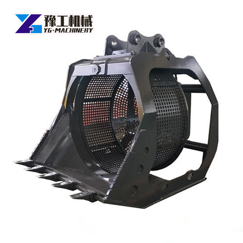
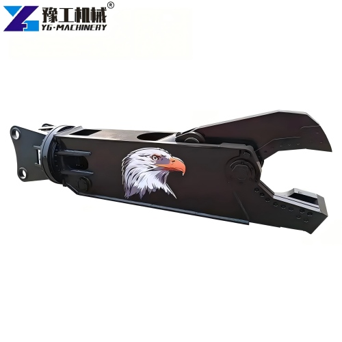
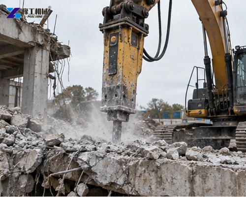
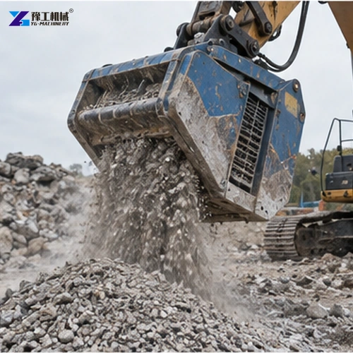
A hydraulic breaker concentrates impact energy for rock and concrete. A pulverizer crushes concrete and separates reinforcement. A steel shear cuts beams, plate and scrap, while a crusher bucket reduces selected rubble using the excavator as a mobile processing platform. None of these descriptions proves suitability for every material.
Choose from the hardest normal section and the desired output. Reinforcement density, embedded plate and contamination can change cycle time sharply. The crusher bucket is useful when mobile reduction matters, but it should not be treated as a substitute for primary structural demolition.
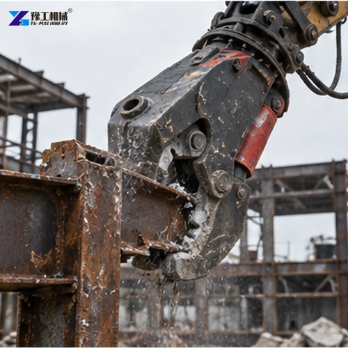
Verified Hydraulic Shear Reference Parameters
Published YG shear data illustrates the carrier range and pressure change across models. Final matching must also confirm flow, back pressure, rotation circuit, boom load chart and coupler geometry.
| Model | Attachment weight | Opening | Working pressure | Applied excavator |
| YG-620 | 620 kg | 334.4 mm | 235 bar | 5–9 t |
| YG-1413 | 1,413 kg | 540 mm | 300 bar | 10–19 t |
| YG-2200 | 2,200 kg | 500 mm | 320 bar | 20–25 t |
| YG-2977 | 2,977 kg | 660 mm | 320 bar | 28–35 t |
| YG-4052 | 4,052 kg | 801 mm | 320 bar | 38–50 t |
Carrier class is only an initial screen. A long-reach boom may have less allowable tool mass than a standard boom, and lifting limits change with radius. Confirm the attachment plus coupler, hoses and any adapter plate against the excavator load chart before ordering.

Coupler Geometry And Hydraulic Interfaces
Record pin diameter, pin-center distance, ear spacing and dipper width directly from the machine or an approved drawing. Model names alone are unreliable across regions and boom options. The excavator quick hitch coupler page provides context, but each attachment interface still needs a dimensioned approval.
Provide auxiliary flow and pressure at the attachment, not only the pump maximum. Confirm hose size, case drain, return restrictions and rotation requirements. Excessive back pressure creates heat and seal problems, while insufficient flow produces slow cycles without proving the attachment is defective.

Stability, Reach And Site Control
Demolition often combines an extended boom, uneven ground and falling material. Check the load chart at the working radius and keep the machine inside the approved orientation. Attachment mass changes the center of gravity before any material is gripped. Establish exclusion zones for debris, hose failure and unexpected structural movement.
The operator needs a clear view of the cutting or crushing point. Cameras, spotters and planned machine positions can reduce blind work. Do not use a rotating tool to drag or side-load the boom unless the manufacturer specifically permits that operation.

Productivity Evidence And Wear Planning
Compare complete cycles: approach, tool engagement, processing, release and repositioning. A large opening may improve placement but does not guarantee faster production if the carrier cannot supply flow or maintain stability. Trial representative material where output is commercially critical.
Ask for replaceable wear parts, blade adjustment, tooth replacement, lubrication points and normal service intervals. The excavator metal shear should be assessed with expected steel grades and sizes. Keep spare hoses, fasteners and high-wear components that match the actual duty.

Quotation Scope And Attachment Change Strategy
The proposal should state bracket or coupler interface, hoses, valves, rotation package, pins, transport frame, guards, tools and spare wear parts. Compare net attachment weight and complete installed weight. Adapters can change geometry and add mass that is absent from a basic catalog figure.
Estimate how often the excavator will change tools. A quick coupler can reduce downtime, but hydraulic and electrical connections still require a safe procedure and positive verification. Frequent changes may justify dedicated carriers or a standardized interface; occasional changes may favor a simpler arrangement.
Transport and storage influence service life. Provide stands that hold tools stable, protect hose ends and keep cutting edges off the ground. Define lifting points and forklift access. An attachment left on uneven rubble is harder to connect safely and exposes pins and couplings to contamination.
Commission with representative material while monitoring carrier stability, oil temperature, cycle time and finished fragment size. Inspect pins, hoses, blades and welds after the trial. The accepted settings should be recorded with the excavator and boom configuration so a later operator does not increase pressure to compensate for wear or unsuitable material.
For a comparable quotation, send one package of evidence: excavator serial information, boom configuration, hydraulic test data, coupler drawing, work photos, material dimensions, required output and expected attachment-change frequency. That allows YG to recommend a staged tool package and identify any assumptions that still require site confirmation.
Selection Errors That Reduce Return
Do not compare opening width without considering usable depth and force location. A jaw may accept a large object near its tips but deliver less force there than close to the pivot. Match the normal bite position to the actual section being processed.
Rotation improves positioning but introduces another hydraulic circuit and service requirement. Confirm whether continuous rotation is necessary, how hoses are protected and what happens if the rotator is side-loaded. A fixed tool may be sufficient for repetitive ground-level work.
High production claims should identify material and measurement basis. Tonnes per hour depends on reinforcement, operator skill, sorting, excavator relocation and downstream loading. Use a trial or a conservative cycle study when the attachment is expected to replace other processing equipment.
Include training on tool limits, inspection and safe isolation. Operators should recognize loose pins, damaged blades, hose abrasion and abnormal heating before a small defect becomes a structural or hydraulic failure.
Pre-Delivery Fit And Function Checks
Before dispatch, compare the fabricated bracket with the approved coupler drawing. Measure pin bores, centers, ear spacing and clearances, and identify hose orientation through the full bucket-linkage movement. A correct static fit can still damage hoses when the attachment curls or rotates near its limit.
Pressure-test hydraulic circuits and verify rotation, jaw movement and holding behavior. Confirm relief settings against both the attachment and carrier limits. Cycle the tool long enough to reveal abnormal heating, leakage or interference, then inspect pins, fasteners, blades and structural welds.
The delivery package should include installed weight, center-of-gravity information where available, connection diagram, operating limits, maintenance intervals and parts identification. Mark lifting points and provide a stable transport stand so the buyer can unload and store the attachment without using the cutting jaws as supports.
On site, commission the tool at reduced speed and pressure before representative work. Recheck hose routing after the first cycles and monitor oil temperature. A documented handover protects productivity because operators know which settings were approved and which material sizes require another tool or working method.
Demolition Attachment FAQ
No. Boom configuration, load chart, hydraulic flow and pressure, coupler dimensions, reach and material duty must also be checked.
Sometimes, but staged projects commonly benefit from different tools for breaking, separation, cutting, sorting and size reduction.
Provide pin diameter, pin-center distance, ear spacing, dipper width and clear photos or an approved interface drawing.
Send excavator model, boom type, load chart, hydraulic data, coupler dimensions, material photos, section sizes, target output and destination.