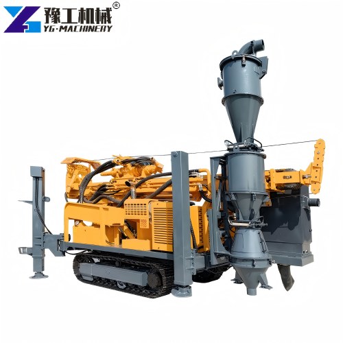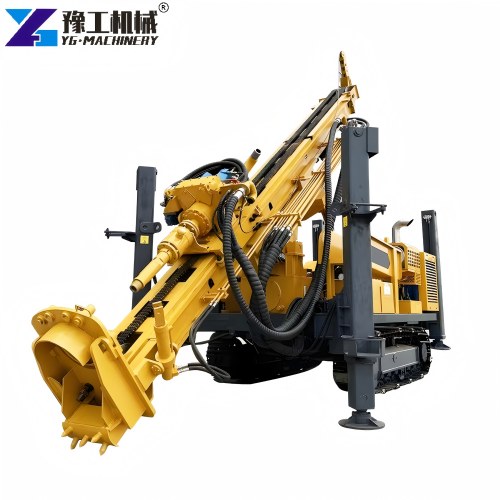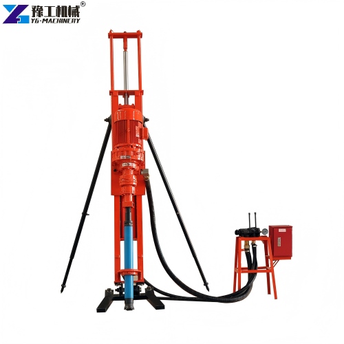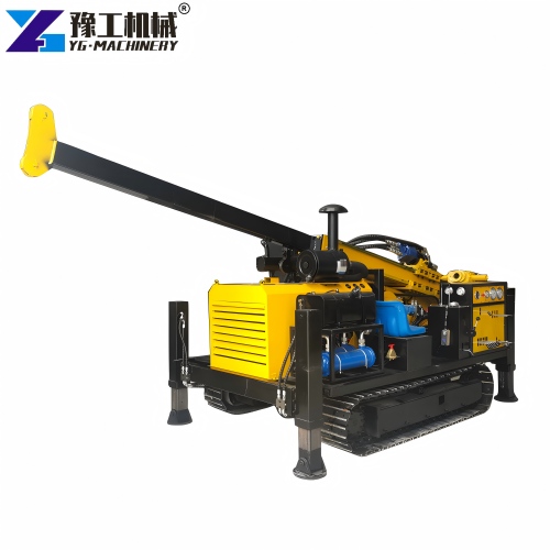
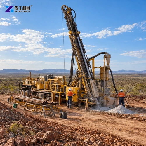
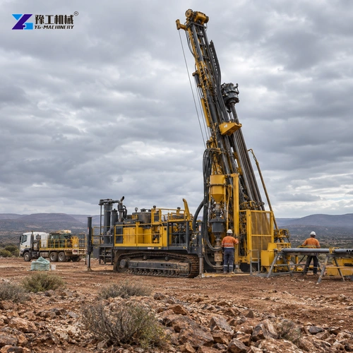
An RC drilling machine is selected not only to make a hole but also to return drill cuttings in a way the exploration team can collect and interpret. In reverse circulation drilling, air travels down the outer annulus of dual-wall pipe and cuttings return through the inner tube toward the surface. That sample path is the reason the method can suit mineral exploration—but it works only when the bit, rods, air supply, cyclone and sample handling are matched to the planned hole.
This guide follows that sample path from the ground to the sample bag, then connects it to rig capacity and the field setup. For the product family, review the YG reverse-circulation drilling rig and the RC drill rig for sale pages. The goal is to help you specify an exploration package, not confuse RC sampling with horizontal utility installation.
How an RC drilling machine returns cuttings through dual-wall drill pipe
The drill bit breaks the formation at the bottom of the hole. Compressed air, or air with a controlled amount of water or drilling fluid where the method and ground allow it, travels down the outer channel formed by the dual-wall drill pipe. At the bit, the returning cuttings enter the inner tube and move upward inside the center passage. At surface, the return is directed through a cyclone or sample-collection arrangement so the crew can collect material at the planned intervals.
Keeping the downflow and sample return paths separated is central to the method. A damaged rod connection, poor seal, incorrect tool assembly or unstable return can compromise the sample stream. The crew should check the rod string and connections during make-up, monitor the return at the surface and keep the sample equipment arranged so cuttings do not mix with earlier intervals or fall outside the collection point.
The drilling plan should specify sample interval, labeling responsibility and any quality checks required by the exploration program. A good drilling rate is not useful if the sample bags are mixed or the interval record is incomplete. This is why rig, rods, air package, cyclone and logging routine need to be reviewed together before mobilization.
Share the hole program and sample interval plan to review whether the RC equipment package supports the required collection workflow.
REVIEW THE RC SAMPLE PATH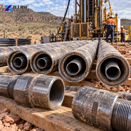
Match RC drilling depth and hole diameter to the exploration program
Start with the target depth, planned hole diameter and expected ground profile for each hole. These determine whether the rig’s mast travel, thrust, lifting force, torque, rod length and selected bit can carry the planned string and tooling. A short reconnaissance hole in accessible ground places different demands on the package than a deeper program with frequent rod handling or changing formations.
The YG150RC is listed with a drilling depth of 150 m and a final-hole diameter range of 110–250 mm. Those values are an initial equipment envelope, not a guarantee for every formation, bit or drilling arrangement. Compare the planned depth and diameter with the selected rod string, bit, cyclone and air supply. Ask the supplier to check any unusual ground, water condition or deviation requirement against the proposed configuration.
Hole angle also changes setup. A vertical hole, inclined exploration hole and irregular access location require different mast positioning and support. Check the permitted inclination and the available setup footprint, then ensure the crew can raise the mast without overhead interference. If the exploration plan has multiple hole sizes or angles, submit the schedule rather than sizing the rig from only the deepest hole.
YG150RC reverse circulation drilling rig specifications
The following values are the stated YG150RC specifications. They help screen the rig against the exploration plan, but the full drilling package also needs the correct dual-wall rods, bit, air supply and sample equipment for the ground and hole design.
| Parameter | YG150RC |
| Product model | YG150RC |
| Crawler-mounted rig weight | 9000 kg |
| Engine power | 125 kW |
| Normal length × width × height | 6750 × 2200 × 2950 mm |
| Ambient temperature range | −10 to 38 °C |
| Nominal drill depth | 150 m |
| End-hole diameter | 110–250 mm |
| Drill angle | −10° to 90° |
| Horizontal hole height | 1.85–2.8 m |
| Drill-head maximum output torque | 8,000 N·m |
| Drill-head output rotation speed, continuous | 30 / 60, 54 / 108 rpm |
| Drill-head output rotation speed, intermittent | 62 / 124, 105 / 210 rpm |
| Feed | 3500 mm |
| Thrust force | 45 kN |
| Lifting capacity | 65 kN |
| Pipe-puller output rotation speed | 40 rpm |
| Pipe-puller maximum output torque | 30,000 N·m |
| Pipe-puller hole-through diameter | 370 mm |
| Auxiliary winch first-layer pull force | 11 kN |
| Auxiliary winch rope diameter | 14 mm |
| Auxiliary winch rope capacity | 60 m |
| Cummins engine | 6BTA5.9-C125 |
| Cummins engine power | 125 kW |
| Maximum rotary speed | 2200 rpm |
| Track walk speed | 1.2 km/h |
| Track unit pressure | <0.05 MPa |
| Climb ability | ≥20° |
Torque, thrust and lifting capacity describe different parts of the rig’s work; they should not be collapsed into one general “power” judgment. Review them against the proposed rods, bit and hole geometry. The rotation-speed entries contain several listed rates, so confirm which settings apply to the selected drilling arrangement. Dimensions, mass and track pressure also matter to transport and positioning, especially on remote or soft sites. Confirm what compressor, cyclone, rods, bits and service components are included rather than assuming the rig body is a complete operating system.
Send the depth and diameter schedule so the YG150RC range can be checked against each planned hole.
CHECK DEPTH AND TOOLING FITSize the air and tooling package for the ground, not just the rig
An RC rig depends on a suitable air supply and correctly matched drilling tools to maintain the intended return path. Provide the formation description, expected water conditions, planned hole diameter and depth, bit type and rod specification. Ask the supplier to identify the compressor capacity and pressure required for that exact combination and whether the compressor is included, supplied separately or expected from the site.
Ground can change during a hole. Fractures, loose layers, water inflow and changes in hardness affect drilling progress and the behavior of the return. The program should define who monitors the return, how the crew responds to loss of sample flow and which operating limits govern adjustments. Do not respond to a poor return by making an unverified change in pressure or tooling; the driller should follow the method and equipment instructions for the actual condition.
Check the bit, inner tube, outer rod, joints and cyclone connection as a single assembly. The inner passage must remain clear enough for the cuttings to return, and the surface separator must direct them to the correct bag or collection container. Keep replacement seals and wear parts appropriate to the chosen string, and document the routine inspection points for the crew.
Provide the formation, water conditions and proposed rod and bit details for an air-package review.
REVIEW THE AIR AND TOOLING PACKAGE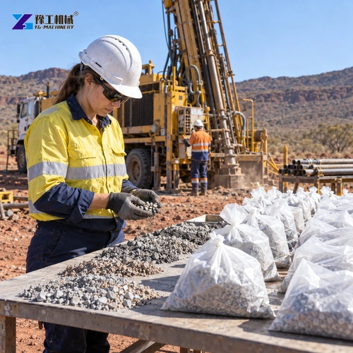
Protect sample quality with a repeatable collection and logging sequence
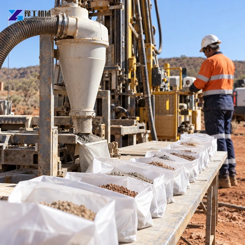
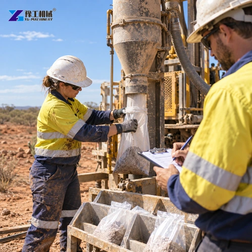
Use a repeatable collection sequence so each sample stays tied to its hole interval:
- Before drilling, prepare and label bags in interval order and assign a person to verify each change.
- Position the cyclone discharge and collection point so cuttings enter the correct container without spilling into another sample.
- At each interval change, confirm the previous sample has cleared the return path before replacing the bag.
- Record the hole number, depth interval, time and drilling observations; note any irregular return, carryover or material loss.
The cyclone and sample splitter must also suit the sample volume and project protocol. Confirm the arrangement in advance when the program specifies a split, sample mass or duplicate procedure; do not silently combine intervals when collection conditions change.
The rig operator, sample technician and geologist need a shared sequence. One person monitors the rig and return, while the assigned sampler handles bag changes and labels. If the return is interrupted or the collection equipment is moved, pause the sample record as the project procedure requires and note the affected interval. This makes later interpretation more defensible than relying on memory after a long shift.
Plan transport, setup and daily service at the RC drilling site
Measure the route from unloading to the first hole, including bridge or axle limits, access width, turning room, slope and ground bearing. Compare the rig’s stated dimensions and mass with the transport arrangement and the site’s ability to support the machine. Identify overhead lines, tree cover or structures that could restrict mast raising, and mark a stable position for the rig, compressor, rods and sample area.
Plan how rods and samples will move without crossing the active machine envelope. Establish a level work area for the cyclone and collection station, protect labeled samples from weather and keep the vehicle route separate from the bagging table. For a remote program, also list fuel, filters, seals, rod-handling tools and the service support available between mobilizations.
The quotation should name the rig configuration and separately list the air compressor, dual-wall drill rods, bits, cyclone or splitter, initial spares, documents, packing and delivery basis. Confirm installation or training scope if requested. A transparent package comparison helps you identify whether each offer is a drilling rig alone or a complete RC sampling system.
Attach the access photos, transport route and sampling requirements for a complete RC drilling package review.
REQUEST AN RC DRILLING PACKAGE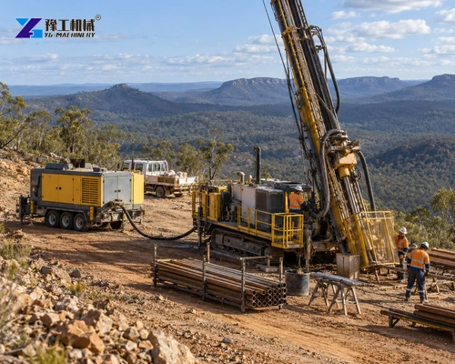
RC drilling machine FAQs
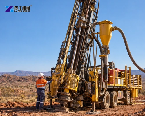
An RC system uses dual-wall drill pipe to send air down the outer passage and return cuttings through the inner tube to a surface collection system. That return path is designed to support controlled sample collection.
The listed YG150RC drilling depth is 150 m. Actual suitability depends on the hole diameter, ground, rod and bit combination, air package and operating setup for the exploration program.
Its stated final-hole diameter range is 110–250 mm. Select the bit and rod arrangement for the planned hole and confirm the complete drilling package before mobilization.
Not necessarily. Ask the supplier to list the compressor, dual-wall rods, bits, cyclone or splitter, spares, tools and delivery scope as separate included or optional items.
Prepare and label containers by interval, assign a person to verify bag changes, allow the previous interval to clear, and record any interrupted or irregular return according to the project logging procedure.
Provide the hole depth and diameter schedule, ground and water conditions, target angle, sample protocol, available access and ground-bearing information, transport route, and whether compressor and sampling equipment are required.
Specify the RC drilling system around the sample objective
The rig is only one part of the exploration result. Share the hole program, formation and sampling protocol so the rig, rods, air supply and collection package can be reviewed as one working system. Use the form below for site and delivery details.