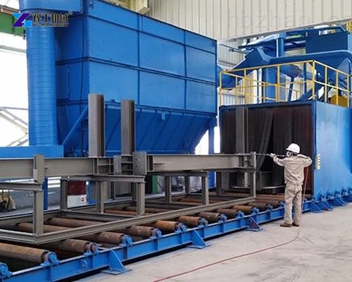
A wheel-blast system cleans or profiles steel by mechanically accelerating abrasive and directing it at the moving workpiece. The shot blasting machine working principle is therefore a connected loop, not only a spinning wheel. Workpiece transport, abrasive dosing, impact, media recovery, separation, storage and dust extraction must remain coordinated for stable cleaning.
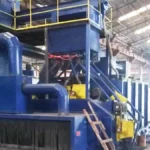
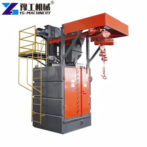
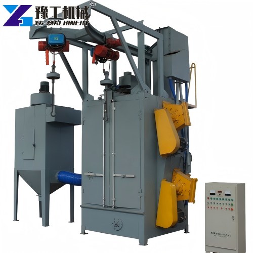
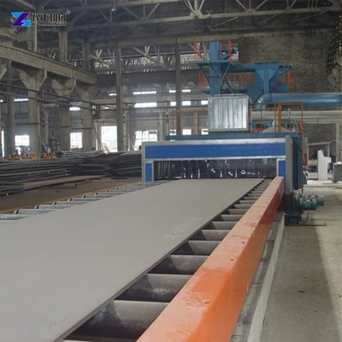
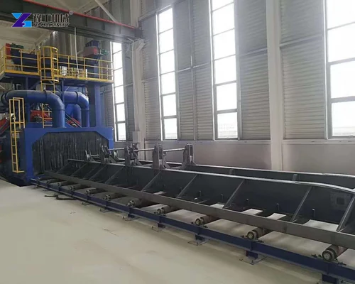
The layout changes with the product. Roller-conveyor machines pass plate or structural sections through an enclosed chamber. Hanger machines rotate suspended parts, while tumble-belt equipment turns batches of smaller components. Mobile floor units travel over a horizontal surface. Each follows the same basic energy and recovery logic, but coverage, sealing and material handling must match the workpiece.
Compare the complete industrial shot blasting equipment layout with the focused roller conveyor shot blasting machine guide when the steel route requires continuous plate or profile handling.
Start the Shot Blasting Machine Working Principle with Workpiece Flow
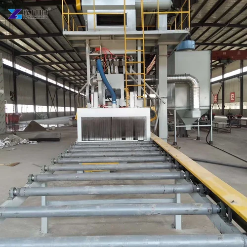
Before abrasive is released, the machine establishes a controlled workpiece path and starts the required extraction and recovery equipment. On a roller-conveyor line, powered rollers move steel through entrance seals and into the blast chamber. Conveyor speed determines exposure time, but the accepted setting also depends on scale, rust, coating, steel shape and the required cleanliness or surface profile.
Workpiece dimensions and weight must remain within the machine’s confirmed opening, roller spacing and handling capacity. Long profiles need support before and after the chamber. Closely nested pieces can shadow one another, while thin or irregular parts may need a different machine type. The handling method is part of cleaning performance because it determines which surfaces face the blast stream.
Send the main project dimensions and material requirement for a model review.
REVIEW MY PROJECT REQUIREMENTS
How the Blast Wheel Accelerates and Directs Abrasive
A metering valve feeds abrasive into the blast-wheel assembly. The impeller and directional control guide media onto rotating blades, which accelerate it toward the workpiece. Wheel position and the directional opening define the main impact zone. Rotation direction, wear condition and correct assembly are essential; a misplaced directional sleeve or control cage can move the pattern away from the intended area.
Impact removes loosely bonded scale, rust, old coating or other surface material and can create a profile for the next process. The result depends on abrasive type and size, wheel speed where adjustable, media flow, angle, exposure time and the starting surface. More media or a slower conveyor is not automatically better because excessive intensity can increase wear or affect the workpiece.

Abrasive Recovery Completes the Shot Blasting Machine Working Principle
After impact, reusable abrasive and removed material fall into the collection system. Depending on the line, screw conveyors carry the mixture to a bucket elevator, which raises it to the separator. The separator removes dust, fines, scale and oversized contamination before serviceable abrasive returns to the storage hopper. Stable separation protects cleaning consistency and reduces unnecessary wheel wear.
The machine then meters cleaned abrasive back to each blast wheel. Operators monitor level and quality rather than adding media blindly. If the circuit loses abrasive, the inspection should find leakage, carryover or a recovery fault. If contaminated media returns to the wheel, check screens, air separation and waste discharge. The recovery loop is both a productivity system and a quality-control point.
| Process stage | Main function | Key confirmation |
| Workpiece handling | Moves or rotates parts through the blast zone | Envelope, weight, support and exposure |
| Abrasive metering | Feeds controlled media to each wheel | Media type, size and flow stability |
| Blast wheel | Accelerates and directs abrasive | Rotation, pattern, wear and wheel position |
| Impact zone | Removes contamination and creates the target surface | Coverage, cleanliness and profile |
| Recovery | Collects spent abrasive and removed material | Leakage, blockage and transfer condition |
| Separation | Removes dust, fines and debris from reusable media | Screening, air balance and waste discharge |
| Dust collection | Extracts fine particles from the closed process | Airflow, filters, seals and safe disposal |


Dust Collection Maintains the Closed Cleaning Process
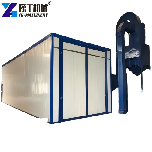
Airflow draws fine dust from the chamber, separator and transfer points to a dust collector. Filters separate particles from the exhaust stream, and the collector’s cleaning system maintains airflow within its designed range. Chamber seals and duct balance help contain dust and abrasive while allowing the workpiece to move. The collector must start before blasting under the machine’s operating sequence.
Dust extraction does not replace housekeeping or safe waste handling. The owner should define filter inspection, dust-hopper emptying and disposal from the actual contaminant and local rules. A falling airflow can reduce visibility and separation quality, while leaks release dust into the factory. These symptoms should be corrected before changing blast-wheel settings to chase a surface result.
Control Surface Finish with Linked Process Variables
The shot blasting machine working principle links the initial condition, abrasive, wheel condition, media flow, wheel position, conveyor speed and number of passes. Approve a representative test piece and record the accepted setup. Inspect all faces, recesses and edges that matter to coating or fabrication. A visual result alone may be insufficient when the project specifies a measurable profile or cleanliness standard.
Change one controlled variable at a time during trials. Slowing the conveyor increases exposure but can reduce throughput and intensify impact. Changing abrasive can affect profile, separation and wear. Replacing wheel parts can shift the blast pattern. The shot blasting machine working principle remains stable only when mechanical condition and process settings are reviewed together.
Share the intended equipment scope so YG can check the configuration and included accessories.

Select a Machine Layout from the Working Principle
Choose roller conveyor for continuous plate, beam and profile handling when the geometry can pass through the opening. Consider hanger equipment for parts that need suspension and rotation, tumble-belt equipment for robust batch components, and mobile equipment for floors or large fixed surfaces. The workpiece task should select the machine family before detailed capacity comparisons begin.
Send workpiece drawings, material, minimum and maximum dimensions, piece weight, hourly quantity, starting contamination, required finish, available floor space and utilities to YG. Ask the proposal to show wheel arrangement, conveyor or handling method, abrasive circuit, separator, dust collector, controls and test scope. This confirms that the supplied line implements the required shot blasting machine working principle for the real steel-cleaning task.
Provide the final site and delivery details when you are ready for a complete quotation.
Shot Blasting Machine Working Principle FAQ for Steel Cleaning
A blast wheel accelerates abrasive at the workpiece, then the machine recovers, separates and recirculates usable media while extracting dust.
No. Wheel blasting uses mechanical acceleration, while pressure or suction blasting propels abrasive with compressed air.
Abrasive, wheel condition, media flow, impact angle, workpiece exposure and starting condition work together.
It keeps fines and debris out of the reusable abrasive stream so media flow and impact remain more consistent.